
Ivysim
Picoblaze Project
For the Spartan3E Starter Kit
 This project provides a robust starting point for any Spartan3E project.
Every design project should start with a sound verification strategy.
Here is a stripped down example of Serial communication between a Picoblaze embedded soft-core and a PC terminal program or testbench with terminal emulator.
This project provides a robust starting point for any Spartan3E project.
Every design project should start with a sound verification strategy.
Here is a stripped down example of Serial communication between a Picoblaze embedded soft-core and a PC terminal program or testbench with terminal emulator.
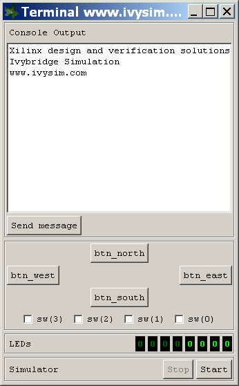
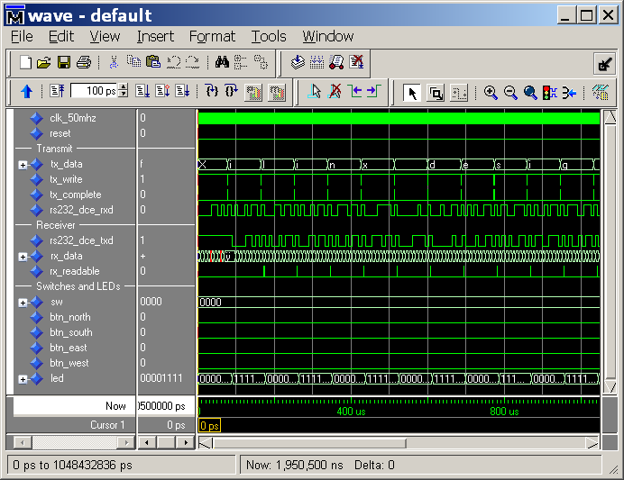
The design can be fully modelled in the simulator. A customised ModelSim window interacts with the testbench to send and receive serially through the design's UART. The test engineer can send messages and see the results during simulation just as if a programmed board was connected through a serial port. Serial transmissions back from the design show up in in the custom ModelSim window.
Switches and LEDs
Some of the controls and LEDs from the Spartan3E Starter Kit are included on the custom window so the tester can interract with the simulation and try things virtually on the fly. Many powerful tests can be coded into the testbench. But it also helps to try what if? tests quickly without having to code more testbenches.
For example: btn_south is connected to the Picoblaze and FIFO resets. The test engineer can reset the whole design at any point during simulation without having to recode, recompile or restart. Just like on the actual hardware.
Picoblaze
In summary the design consists of RX UART -> FIFO -> Picoblaze -> FIFO -> TX UART. Also, switches/buttons are mapped to Picoblaze in-port 02, LEDs are mapped to out-port 02.
The archived assembly file simply reads the RX FIFO as data is available and writes it to the TX FIFO. The LEDs toggle between 00001111 and 11110000 whenever a byte is written out. If sw(0) is set then lowercase letters are changed to uppercase.
The Plan
 This example project is intended as a platform to further explore Picoblaze-based design and verification.
Try making small changes to the RTL or assembler code and resimulate.
This example project is intended as a platform to further explore Picoblaze-based design and verification.
Try making small changes to the RTL or assembler code and resimulate.
The assembler source file can be found in the source subdirectory. A Tcl script is provided to make recompiling quick and simple. There's no need to install a Tcl interpreter, perhaps you didn't know but, you already have one with the Xilinx installation. Provided Xilinx's bin/nt directory is in the path variable you simply need to double-click the compile_rom.bat batch file. When your code changes assemble correctly just type the command "go" in ModelSim to restart.
Picoblaze Debugger
The Ivysim Debugger for Picoblaze is featured in this project. So you can set break points and step through the Picoblaze assembly code line by line. You can find more instructions on the debugger page.
Download
Try out this example. All you need is Xilinx 8.3i or later and a recent copy of ModelSim. Xilinx Edition, even the free ModelSimXE III/Starter version, works. Grab the zipfile and copy it onto your Windows machine. There are two batch files, clearly labelled, giving you a flying start.
| Download |
| picoblaze_debugger.zip |
Programming the FPGA
A copy of Ivysim Quick ISE is included. Double-click quickise.bat to launch it. Choose Download from the Processes menu or use shortcut Ctrl-6. Connect the USB download cable and power your starter kit first.
Connect the starter kit DCE 9-pin D-type socket to your PC using a serial lead. Set up Hyperterminal or another terminal application to 115200 baud, eight data bits, one start bit, one stop bit.
Suggested Exercise
Implement a simple command interpreter. For example: Program the Picoblaze to interpret simple commands such as "read 00" and print the contents of port 00. Internal signals can be mapped to Picoblaze ports and easily accessed through one serial pin. Implement a write command then internal registers can be modified through the serial port after FPGA configuration.